![]()
![]()
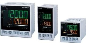
The DB600 series is a digital indicating controller with the indicating accuracy ±0.1% and the control cycle of approximately 0.1seconds.
Various functions including universal input and multiple setting values (8types) are provided as standard.
There are three types of size.
DB670 --- 96 x 96mm, DB650 --- 96 x 48mm
DB630 --- 48 x 48mm
|
Excellent control performance PID control algorithm and Z control algorithm are selectable according to the application. PID control algorithm: Conventional control method Z control algorithm: Our new algorithm (patent pending) which has evolved the PID control method. Especially, the effect can be expected such as overshoot suppression and speedy recovery in the event of disturbance control (during opening and closing of the electric furnace). |
|
Large easy-to-view 5-digit 11 segments display. Process value (PV) and set value (SV) are displayed by large easy-to-view 5-digit display indicators. The resolution of 0.1°C is enabled high-definition and highly sophisticated. |
|
Operability inheriting previous models. The controller inherits the setting screen and the settings screen adopting the LCD (liquid-crystal-display) which has been familiarized for long time. Furthermore, the screens have become high-definition and highly sophisticated. |
|
24V power supply voltage type available The power supply voltage 24V (AC/DC) type, which is advantageous in respect of safe, is available. |
|
Various operating status in one glance Operating condition Setting value ramp (option for program model) Analog bar output |
|
Universal input Various measurement ranges of DC voltage (up to maximum 10V) inputs, DC current input, thermocouple inputs and resistance thermometer inputs have been built-in. |
|
Program Operation (option) Set 4 patterns, 12 steps. |
|
Confirming to international safety standards and European directives (CE) (conformity pending) The controller is in conformity with European directives (CE), and is UL and c-UL approved. |
|
Engineering software (Standard attached) By connecting to PC with exclusive USB engineering cable (RZ-EC3) (sold separately), you can load/save parameter data and acquisition. |
Control algorithm
| Model | Specification | Remarks |
| DB670XXXXXXX0X | PID Control | |
| DB67ZXXXXXXX0X | Z Control |
| Control output 1 |
| Model | Specification | Remarks |
| DB67X⬚XXXXX0X |
| ⬚: |
1: ON-OFF pulse output type 2: ON-OFF servo output type 3: Current output type 5: SSR drive pulse output type 6: Voltage output type |
| Control output 2 (option) |
| Model | Specification | Remarks |
| DB67XX⬚XXXXX0X |
| ⬚: |
0: None 1: ON-OFF pulse output type *1 3: Current output type *1 5: SSR drive pulse output type *1 6: Voltage output type *1 |
| Communication interface + 5 External signal input points / 5 Event output points (option) |
| Model | Specification | Remarks |
| DB67XXX⬚XXXX0X |
| ⬚: |
0: None A: RS422A + 5 External signal input points (DI 1 to 5) S: RS485 + 5 External signal input points (DI 1 to 5) B: RS422A + 5 Event output points ‹open corrector output›(EV 5 to 9) C: RS485 + 5 Event output points ‹open corrector output›(EV 5 to 9) D: 5 External signal input points (DI 1 to 5) E: 5 Event output points ‹open corrector output›(EV 5 to 9) |
| Transmission signal output + 2 Event output points (option) |
| Model | Specification | Remarks |
| DB67XXXX⬚XXX0X |
| ⬚: |
0: None 1: 4 to 20mA 2: 0 to 1V 3: 0 to 10V 4: 4 to 20mA + 2 Event output points ‹mechanical relay output›(EV3, 4)*1 5: 0 to 1V + 2 Event output points ‹mechanical relay output›(EV3, 4))*1 6: 0 to 10V + 2 Event output points ‹mechanical relay output›(EV3, 4)*1 7: 2 Event output points ‹mechanical relay output›(EV3, 4)*1 |
| Remote signal input + 2 External signal input points (option) |
| Model | Specification | Remarks |
| DB67XXXXX⬚XX0X |
| ⬚: |
0: None 5: 4 to 20mA 6: 0 to 1V 7: 0 to 10V 8: 4 to 20mA + 2 External signal input points (DI6, 7)*2 9: 0 to 1V + 2 External signal input points (DI6, 7)*2 A: 0 to 10V + 2 External signal input points (DI6, 7)*2 B: 2 External signal input points (DI6, 7)*2 |
| Programming function (option) |
| Model | Specification | Remarks |
| DB67XXXXXX⬚X0X |
| ⬚: |
-: None P: Available |
| 2 Event output points + Heater disconnection detection |
| Model | Specification | Remarks |
| DB67XXXXXXX⬚0X |
| ⬚: |
0: None 1: 2 Event output points ‹mechanical relay output›(EV1, 2)*3 2: 2 Event output points ‹mechanical relay output›(EV1, 2)*3 + Heater disconnection detection *4 |
| Power voltage |
| Model | Specification | Remarks |
| DB67XXXXXXXX0⬚ |
| ⬚: |
A: 100 to 240V AC D: 24V AC/DC |
*1 It can be specified when Control output 1 is "1", "3", "5" or "6".
*2 It can be specified when 2 Event output points + Heater disconnection is "0" or "1".
*3 When specification with Control output 2, number of event output points is only 1 point (EV2)
*4 It can be specified when Control output 1 and Control output 2 are "1" or "5"
and Remote signal input + 2 External signal input points is "0", "5", "6" or "7".
However, if Control output 1 and Control output 2 are both "1" or "5", it can be operated with Control output 1.
Control algorithm
| Model | Specification | Remarks |
| DB630XXX00XX0X | PID Control | |
| DB63ZXXX00XX0X | Z Control |
| Control output 1 |
| Model | Specification | Remarks |
| DB63X⬚XX00XX0X |
| ⬚: |
1: ON-OFF pulse output type 3: Current output type 5: SSR drive pulse output type 6: Voltage output type |
| Control output 2 (option) |
| Model | Specification | Remarks |
| DB63XX⬚X00XX0X |
| ⬚: |
0: None 3: Current output type 5: SSR drive pulse output type 6: Voltage output type |
| Communication interface + 1 External signal input points / 5 External signal input points / 5 Event output points (option) |
| Model | Specification | Remarks |
| DB67XXX⬚00XX0X |
| ⬚: |
0: None S: RS485 + 1 External signal input points (DI 1) D: 5 External signal input points (DI 1 to 5) E: 5 Event output points ‹open corrector output›(EV 5 to 9) |
| Programming function (option) |
| Model | Specification | Remarks |
| DB63XXXX00⬚X0X |
| ⬚: |
-: None P: Available |
| 2 Event output points |
| Model | Specification | Remarks |
| DB63XXXX00X⬚0X |
| ⬚: |
0: None 1: 2 Event output points ‹mechanical relay output›(EV1, 2)*1 |
| Power voltage |
| Model | Specification | Remarks |
| DB63XXXX00XX0⬚ |
| ⬚: |
A: 100 to 240V AC D: 24V AC/DC |
*1 When specification with control output2, number of event output points is only 1 point (EV2)
Control algorithm
| Model | Specification | Remarks |
| DB650XXXXXXX0X | PID Control | |
| DB65ZXXXXXXX0X | Z Control |
| Control output 1 |
| Model | Specification | Remarks |
| DB65X⬚XXXXX0X |
| ⬚: |
1: ON-OFF pulse output type 2: ON-OFF servo output type 3: Current output type 5: SSR drive pulse output type 6: Voltage output type |
| Control output 2 (option) |
| Model | Specification | Remarks |
| DB65XX⬚XXXXX0X |
| ⬚: |
0: None 1: ON-OFF pulse output type *1 3: Current output type *1 5: SSR drive pulse output type *1 6: Voltage output type *1 |
| Communication interface + 5 External signal input points / 5 Event output points (option) |
| Model | Specification | Remarks |
| DB65XXX⬚XXXX0X |
| ⬚: |
0: None A: RS422A + 5 External signal input points (DI 1 to 5) S: RS485 + 5 External signal input points (DI 1 to 5) B: RS422A + 5 Event output points ‹open corrector output›(EV 5 to 9) C: RS485 + 5 Event output points ‹open corrector output›(EV 5 to 9) D: 5 External signal input points (DI 1 to 5) E: 5 Event output points ‹open corrector output›(EV 5 to 9) |
| Transmission signal output + 2 Event output points (option) |
| Model | Specification | Remarks |
| DB65XXXX⬚XXX0X |
| ⬚: |
0: None 1: 4 to 20mA 2: 0 to 1V 3: 0 to 10V 4: 4 to 20mA + 2 Event output points ‹mechanical relay output›(EV3, 4)*1 5: 0 to 1V + 2 Event output points ‹mechanical relay output›(EV3, 4))*1 6: 0 to 10V + 2 Event output points ‹mechanical relay output›(EV3, 4)*1 7: 2 Event output points ‹mechanical relay output›(EV3, 4)*1 |
| Remote signal input + 2 External signal input points (option) |
| Model | Specification | Remarks |
| DB65XXXXX⬚XX0X |
| ⬚: |
0: None 5: 4 to 20mA 6: 0 to 1V 7: 0 to 10V 8: 4 to 20mA + 2 External signal input points (DI6, 7)*2 9: 0 to 1V + 2 External signal input points (DI6, 7)*2 A: 0 to 10V + 2 External signal input points (DI6, 7)*2 B: 2 External signal input points (DI6, 7)*2 |
| Programming function (option) |
| Model | Specification | Remarks |
| DB65XXXXXX⬚X0X |
| ⬚: |
-: None P: Available |
| 2 Event output points + Heater disconnection detection |
| Model | Specification | Remarks |
| DB65XXXXXXX⬚0X |
| ⬚: |
0: None 1: 2 Event output points ‹mechanical relay output›(EV1, 2)*3 2: 2 Event output points ‹mechanical relay output›(EV1, 2)*3 + Heater disconnection detection *4 |
| Power voltage |
| Model | Specification | Remarks |
| DB65XXXXXXXX0⬚ |
| ⬚: |
A: 100 to 240V AC D: 24V AC/DC |
*1 It can be specified when Control output 1 is "1", "3", "5" or "6".
*2 It can be specified when 2 Event output points + Heater disconnection is "0" or "1".
*3 When specification with Control output 2, number of event output points is only 1 point (EV2)
*4 It can be specified when Control output 1 and Control output 2 are "1" or "5"
and Remote signal input + 2 External signal input points is "0", "5", "6" or "7".
However, if Control output 1 and Control output 2 are both "1" or "5", it can be operated with Control output 1.
or more
| Input Specifications | |
| Input type: |
Thermocouple B, R, S, N, K, E, J, T, U, L, WRe5-WRe26, W-WRe26, Platinel II, PtRh4--PtRh20, Au-Pt DC Voltage ±20mV, ±100mV, ±5V, ±10V Resistance thermometer Pt100, JPt100, Pt50 |
| Measuring Range: | Thermocouple 16ranges, DC voltage 4ranges, Resistance thermometer 5ranges |
| Temperature unit: | °C |
| Accuracy rating: | ±0.1% of FS ±1 digit of measuring range, For details, refer to "measuring ranges and accuracy ratings" in PS sheet |
| Reference junction compensation accuracy: |
±1.0°C (ambient temperature 23°C ± 10°C) ±2.0°C (temperature other than above) |
| Sampling rate: | Approx. 0.1 seconds |
| Burnout: |
Upper limit burnout is provided for thermocouple, resistance thermometer and DC voltage (20mA) only as standard. Output 1 produces PV abnormal output and output 2 is fixed to 0% when burnout occurs. Upper limit alarm event is output. |
| Input impedance: |
Thermocouple 1MΩ or more DC voltage Approx. 1MΩ |
| Allowable signal source resistance: |
Thermocouple -------- 100Ω or less DC voltage (mV) ----- 100Ω or less DC voltage (V) -------- 300Ω or less |
| Allowable wire resistance: |
Resistance thermometer 10Ω/1 wire or less (resistance of 3 wires should be equal to one another) |
| Resistance thermometer measurement current:: | Approx. 1mA |
| Maximum allowable input: |
Thermocouple ------------ ±10V DC DC voltage (mV) --------- ±10V DC DC voltage (V) ------------ ±20V DC Resistance thermomter ±5V DC |
| Maximum common mode voltage: | 30V AC |
| Common mode rejection ratio: | 130dB or more (50/60Hz) |
| Series mode rejection ratio: | 50dB or more (50/60Hz) |
| Control Specifications | |
| Control interval: | Approx. 0.1 seconds |
| Output type: |
ON-OFF pulse output, ON-OFF servo output (DB650 & DB670 only), Current output, SSR drive pulse output, Voltage output |
|
ON-OFF pulse type: 1. Contact type 2. Pulse cycle 3. Contact capacity |
1. 1a contact 2. Approx. 1 to 180 seconds 3. Resistive load --- 240V AC 3A, 30V DC 3A Inductive load --- 240V AC 1.5A, 30V DV 1.5A Minimum load --- 5V DC 10mA |
|
ON-OFF servo output type: 1. Contact type 2. Feedback resistance 3. Contact capacity |
1. 1a contact 2. 100Ω to 2KΩ 3. Resistive load --- 240V AC 3A, 30V DC 3A Inductive load --- 240V AC 1.5A, 30V DV 1.5A Minimum load --- 5V DC 10mA |
|
Current output type: 1. Output specification 2. Load resistance |
1. 4 to 20mA DC 2. 600Ω or less |
|
SSR drive pulse output type: 1. Pulse cycle 2. Output specification |
1. Approx. 1 to 180 seconds 2. ON --- 12V DC ±20%(Load current 21mA or less) OFF --- 0.8V DC or less |
|
Voltage output type: 1. Output specification 2. Output resistance 3. Load resistance |
1. 0 to 10V DC 2. Approx. 10Ω 3. 50KΩ or more |
|
Specification with 2 outputs: 1. Output type 2. Insulation 3. Control system |
1. Any combination between ON-OFF pulse output, ON-OFF servo output current output, SSR drice pluse output and voltage output is possible. 2. Non-isolated between 2 outputs(ON-OFF pulse output type is excluded) 3. Z, PID |
| Display Specifications | |
| Display: | Segment type LCD (LED backlight) |
| General Specifications | |
| Rated power voltage: |
100 to 240V AC (±10%) 24V DC (±10%) |
| Rated power supply frequency: | 50/60Hz (±2%) |
|
Maximum power consumption: 1. 100 to 240V AC (without option) 2. 100 to 240V AC (with option) 3. 24V AC/DC (without option) 4. 24V AC/DC (with option) |
1. DB630 --- 100V AC 4VA, 240V AC 5VA DB650 --- 100V AC 4VA, 240V AC 6VA DB670 --- 100V AC 4VA, 240V AC 6VA 2. DB630 --- 100V AC 5VA, 240V AC 7VA DB650 --- 100V AC 7VA, 240V AC 10VA DB670 --- 100V AC 9VA, 240V AC 12VA 3. DB630 --- 24V AC 3VA, 24V DC 2W DB650 --- 24V AC 4VA, 24V DC 3W DB670 --- 24V AC 4VA, 24V DC 3W 4. DB630 --- 24V AC 4VA, 24V DC 3W DB650 --- 24V AC 7VA, 24V DC 5W DB670 --- 24V AC 8VA, 24V DC 6W |
| Countermeasure against power failuer: | Store setting contents in no-volatile memory. (Rewire: 1 million times) |
| Insulation resistance: |
Between the primary and secondary terminals 20MΩ (500V DC) *Primary terminals: Power terminal (100 to 240V AC) EV1 to 4 output terminals (relay output), ON-OFF pulse output terminal (relay output), ON-OFF servo output terminal (M3, M2, M1) Secondary terminal: Power terminal (24V AC/DC), all terminals expect primary terminals |
| Withstand voltage: |
Between the primary and secondary terminals 1500V AC (1 minute) Refer to "Insulation resistance" in PS sheet for the primary and secondary terminals. |
| Casing: | Fire-retardant polycarbonate (UL94V-2) |
| Color: | Gray |
| Mounting: | Panel mounting |
| External dimensions: | Refer to PS sheet |
| Weight: | Refer to PS sheet |
| Terminal screw: | M3.0 |
| Engineering port: |
DB630 At the bottom of case DB650 At the top of the case |
| Reference operating conditions | |
| Ambient temperature: | 23°C ±2% |
| Ambient humidity: | 55%RH ±1% (no condensation) |
| Power voltage: | 100V AC ±1% |
| Power supply frequency: | 50/60Hz ±0.5% |
| Mounting orientation: | Backward / forward ±3°, laterally ±3° |
| Installation height: | Below 2000m |
| Vibration: | 0m/s2 |
| Shock: | 0m/s2 |
| Installation condition: | Single panel mounting (space required around) |
| Wind: | None |
| External noise: | None |
| Warm up time: | At least 30 minutes |
| Normal operating conditions | |
| Ambient temperature: | -10°C to 50°C (-10°C to 40°C for close installation) |
|
Maximum ambient humidity: (ambient temperature -10 to 31°C) |
90%RH (no condensation) *Decreases linearly from 90%RH at 31°C, or to 50%RH at 50°C |
| Minimum ambient humidity: | 20%RH |
| Power voltage: |
100 to 240V AC (90 to 264V AC) 24V AC/DC (21.6 to 26.4V AC/DC) |
| Power supply frequency: | 50/60Hz ±2% |
| Mounting orientation: | Backward / forward ±10°, laterally ±10° |
| Installation height: | Below 2000m |
| Vibration: | 0m/s2 |
| Shock: | 0m/s2 |
| Vibration: | 0m/s2 |
| Installation condition: | Panel mounting (space above and below) |
| External noise: | None |
| Ambient temperature variation ratio: | 10°C/hour or less |
| Standard | |
| Safety: |
EN61010-1 (CE marking) UL61010-1 2nd edition (UL) CAN/CSA C22.2 No. 61010-1 (c-UL) Setup category: CAT.II, pollution degree:2 |
|
EMC applicable: CE marking |
EN61326-1 ClassA Table2 EN5011 Class A Group1 EN61000-3-2 Class A EN61000-3-3 *Indication or output value varies by the amount equivalent to ±10% of FS or ±2mV, whichever is larger, during testing. |
| Structure: |
Casing protection IEC60529 IP65 equivalent (Unapplied for close installation) (CE, UL, c-UL are contormity pending) |
| Transmission signal output (option) | |
| Output points: | 1 point |
| Output signal: |
4 to 20mA DC (load resistance 400Ω or less) 0 to 1V DC (load resistance 50KΩ or more) 0 to 10V DC (load resistance 50KΩ or more) |
| Accuracy: | ±0.3% of full scale |
| Output updating interval: | Approx. 0.1 seconds |
| Insulation: |
Non-isolated between the adjustment output 1 and 2 (ON-OFF pulse output type excluded) |
| Sampling rate: | Approx. 0.2 seconds |
| Remote signal input (option) | |
| Input point: | 1 point |
| Input signal: |
4 to 20mA DC (input impedance Approx.50Ω) 0 to 1V DC (input impedance Approx.500KΩ) 0 to 10V DC (input impedance Approx.100KΩ) |
|
Maximum allowable input: 1. DC current 2. DC voltage |
1. ±30mA or less, ±1.5V DC or less 2. ±20V DC or less |
| Accuracy | ±0.3% of full scale ± 1digit |
| External signal switch | R/L (remote / Local) |
| Communication interface (option) | |
| Input point: |
DB630 --- 5 points maximum, COM shared DB650 --- 7 points maximum, COM shared DB670 --- 7 points maximum, COM shared |
| Protocol: |
MODBUS-RTU, MODBUS-ASCII, Private (used fpr digital transmission/digital remote input) |
| Function: | Host communication/digital transmission/digital remote input) |
| Alarm Specifications | |
| Number of alarm points: | 2 points |
| Alarm types: |
Absolute value alarm, deviation alarm, absolute value deviation alarm, set point alarm, output value alarm, heater disconnection alarm (only for the case adjustment output 1 uses ON-OFF pulse output or SSR drive pulse output), time 1, timer 2, FAIL |
| Heater disconnection detection (option) | |
| Functions: | Measure heater current using an external current transformer (CT) to detect disconnection. |
| Input points: | 1 point |
| Input signals: |
5.0 - 50.0A (50/60Hz) *Specified external current transformer (CT) required. |
| Accuracy: | ±5.0% of FS ±1digit |
| External signal input (option) | |
| Input point: |
DB630 --- 5 points maximum, COM shared DB650 --- 7 points maximum, COM shared DB670 --- 7 points maximum, COM shared |
| Input signal | No voltage contact |
| External contact capacity: | 5V DC 2mA |
| Function: |
Constant value operation RUN/READY switch, AUTO/MAN switch, preset manual, timer 1, timer 2, alarm event reset, execution No.selection, program/constant value operation switch, program operation RUN/STOP switch, program operation ADVANCE, program operation RESET, program oattern selection |
| Performance Specification Sheet | Digital Indicating Controller | DB600 Series | Download |